Generating a CAD model for a fully-coupled earthquake-tsunami simulation#
Here we present a workflow for generating a CAD model of the Eastern Aegean Sea, including ocean and topography to be used in fully-coupled earthquake-tsunami simulations of the 2020 Aegean Sea earthquake. We use scripts from SeisSol/Meshing. To best follow this tutorial, we suggest adding the geometry script folder to the path:
export PATH=$PATH:~/SeisSol/Meshing/creating_geometric_models
Please consider running git pull in SeisSol/Meshing to pull the latest version of the scripts, if the repository is not newly cloned. You may also install required python modules with pip3 install -r requirements.txt (or if you use anaconda, conda install –file requirements.txt). This tutorial has been tested with SimModeler10.0-211122. Note that one specific step requires SimModeler11.0-220403-dev, but another step of the workflow fails with the dev version.
Creating topography and boxes#
First, we download topography and bathymetry data from GEBCO (http://www.gebco.net/), and we triangulate it into a GoCad ts file.
Note that we downsample the topography data by a factor 2 for dealing with a reasonable size dataset in this tutorial.
Note also that we use a custom transverse Mercator roughly centered at the domain center.
With the option
--change_zero_elevation 1.0, we move the nodes with zero elevation to 1.0 m. This avoids having to intersect locally coplanar surfaces.With the option
--smooth 100, we replace the elevation of topography nodes with z coordinates in the range \(\pm\) 100 m by spatially smoothed (using a 2D Gaussian kernel) values.
This facilitates the intersection of the sea surface with the topography and allows a smoother coastline (which can else have a saw-tooth shape due to rounded elevation data, stored as integers in Gebco files).
myproj='+proj=tmerc +datum=WGS84 +k=0.9996 +lon_0=26.25 +lat_0=37.75'
topofile='gebco_2021_n39.5_s36.0_w23.5_e29.0.nc'
create_surface_from_rectilinear_grid.py $topofile topo.ts --proj "$myproj" --sub 2 --smooth 100 --change_zero_elevation 1.0
Next, we generate a mesh of 2 boxes, one for defining the water layer and the other for defining the domain region.
generate_box.py box_water_layer.stl --hdim " -40e3" 93e3 " -10e3" 53.0e3 --zdim " -10e3" 0 --meshSize 600.
generate_box.py --proj "$myproj" --rangeFromTopo $topofile box_domain.stl --zdim " -200e3" 10e3 --shrink 0.9
Intersecting topography and sea-surface#
Then we load box_water_layer.stl and topo.ts into SimModeler (Import Discrete Data, select both files (press Shift), and unclick all options except Find edges by face normals, with Normal Angle 80, a value high enough to detect the box, but not creating new faces in the topography surface).
We then do Unions Parts (Tolerance 0.1, smaller than the change_zero_elevation parameter) with Parts topo and box_water_layer.
This leads to the creation of 3 regions and 1 face.
Region 3 is the solid Earth below the sea floor, region 4 is the larger ocean region, and region 5 is the small dark green water region.
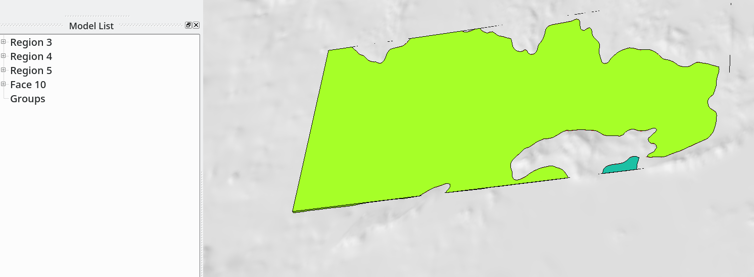
Fig. 10 Three-regions model obtained after intersecting bathymetry and water-layer box.#
The next step is to delete the solid Earth regions 3 (note that region numbers may differ). Use Discrete->Delete add regions 3, and press Ok.
At this point, the model has 2 regions and 1 surface.
We can double-check the quality of the intersections with Prepare->Remove Small features.
Here the shortest edge in the model is 139 m, which is large enough.
If this was not the case, small edges can be identified, and the associated node of the not yet intersected topography moved (with Discrete->Deform Face).
Then the full workflow described above needs to be followed again with the updated topography (and hopefully the short edge has been suppressed).
The next step consists of loading domain_box.stl and intersecting it with the current model.
The union is done with SimModeler11.0-220403-dev (as it fails with SimModeler10.0).
We then clean the model of the upper part of domain_box, the part of the topography outside the domain box, and the smaller water layer region.
The sea floor below the removed smaller water layer region can be merged with Discrete->Combine Faces).
The obtained model has 2 regions.
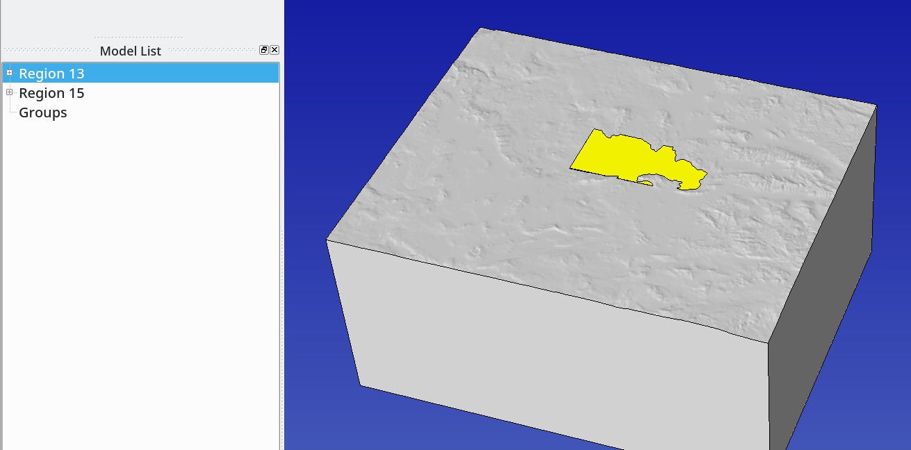
Fig. 11 Two-regions model of the Eastern Aegean Sea area, including a water layer.#
Enforcing minimum depth on seafloor surface#
Unfortunately, the water layer of the model described above is not meshable by SimModeler, because at some locations, the sea floor is too close to the sea surface.
Because of that, the error Cannot resolve intersecting mesh is raised, even when using a small mesh size of 100 m.
To deal with this problem, we extract the mesh of the sea floor and increase the sea floor depth where it is very close to the sea surface.
This is done with:
Mesh->Miscellaneous->Use Discrete Geometry Meshon the sea-floor andMesh->Element Type->No Mesh->Entityon all other surfaces.Volume Meshingshould be removed.Mesh->Generate MeshMesh->Export Mesh: Filename seafloor.inp.
Then we enforce the minimum depth of the seafloor with:
convertInp.py seafloor.inp seafloor.stl --enforce_min_depth 40
Note that the minimum depth of 40 m applies only on nodes of the seafloor triangulation, that is the effective depth varies linearly between these nodes and the coast. A value of 40 m makes sense due to the coarse (horizontal) resolution of the topography here used (900 m resolution). For example, we see that with 25 m, SimModeler can successfully mesh the water layer only with a mesh size smaller than 200 m, while a value of 40 m allows at least 1 km. In case of a finer topography resolution, a smaller value should be used.
The next step is to generate an stl file (other_surfaces.stl) with all other surfaces from the model using the workflow presented above (without --enforce_min_depth option but with --isolate option).
convertInp.py other_surfaces.inp other_surfaces.stl --isolate
Both stl files can finally be combined into a stl file using cat:
cat seafloor.stl other_surfaces.stl > new_model.stl
Once loaded into SimModeler (untick all when importing), 2 regions are detected and the shallow water can be successfully meshed, even with large mesh size (e.g. 1 km in the water layer).
Dealing with union errors#
Unfortunately, unions may fail.
At best, a descriptive error is issued by SimModeler, e.g.:
Error: Code: 604 String: edge 72 has tangent faces at point (61781.436490285792, 3066.1427893521077, -2.2204460492502381e-16)
In this case, we can overcome the problem by manually moving a node of one of the surfaces intersected close to the location of the error with Discrete->Deform Face.
The error Error: Code: 60 String: General error may also be raised, for which there is currently no obvious workaround, except trying to change the mesh size or the dimension of one of the intersected objects.
Hopefully, these error messages will be improved in the future.