Gmsh
Introduction
Gmsh is an open-source mesher, able to generate quality meshes for not too complex models. Contrary to SimModeler, it can build geometric models from scratch. It is particularly useful for simple idealized models, e.g. planar fault, no topography. Two examples of model generation using Gmsh are provided at this link. The purpose of this tutorial is not to explain all functions of gmsh, but to describe the features useful for setting a model and getting a mesh for SeisSol.
Coarsening the mesh
The Attractor Field feature is used to coarsen the mesh away from the fault. As it requires a “Ruled Surface”, we define an artificial “Ruled Surface” used only for that feature. The rate of coarsening is defined empirically by combining a linear increase of the mesh size in the near field and a quadratic increase in the far size. Example:
Field[2].F = Sprintf("0.1*F1 +(F1/5.0e3)^2 + %g", lc_fault);
Boundary conditions
The free-surface (resp. dynamic rupture, resp. absorbing) boundary conditions are set using Physical Surfaces 101 (resp. 103, resp. 105). The volumes should also be put into Physical Volume to be exported into the mesh. Here is an example from tpv33:
Physical Surface(101) = {252, 258, 260, 262};
Physical Surface(105) = {242, 244, 246, 248, 250, 254, 256};
Physical Surface(103) = {2, 3, 4};
Physical Volume(2) = {276,278};
Physical Volume(3) = {274};
Generating the mesh
gmsh test.geo -3 -optimize -format neu
Note that the ‘-format neu’ is only possible since gmsh 4.0 For previous versions, we used gmsh2gambit on the msh mesh generated with:
gmsh test.geo -3 -optimize
gmsh to SimModeler
gmsh ___.geo -2 -o ___.stl with different surfaces listed in the physical surface listing).
Then the solid name attribute of the stl files has to be modified. Finally, the stl files can be
merged into a single stl file, to be opened in SimModeler.mirroring a mesh
In order to get maximum accuracy, it is sometimes necessary (e.g. for benchmarks) to mirror a mesh. To get a mirrored mesh, a half mesh is first generated. The half mesh is then converted to PUML format using PUMGen (if not already in this format). Finally, this script allows creating the mirrored mesh
Add topography in GMSH
The roughed fault interface model is generated with Gmsh is complicated than planar faults in previous sections. There are 5 steps to generate the model.
1.Create topography data. The format is the following:
Line 1: num_x, num_y
Line 2 to nx: positions of nodes along the strike (in meters)
Line nx+3 to ny+nx+3: positions of nodes along the downdip (in meters)
Line to the end: the topography of each node (nx\*ny, in meters)
Save this file as mytopo.dat.
2.Make a model with a plane surface first (step1.geo).
cl = 1;

// This file builds a rectangular box domain region which is exactly the same as topographic data.

level = 0.0; // horizontal elevation
region = 220; // range in meter
depth = 100;

Point(1) = { 0.5*region, 0.5*region, level, cl} ; //water level
Point(2) = { -0.5*region,0.5*region, level, cl} ;
Point(3) = { -0.5*region,-0.5*region, level, cl} ;
Point(4) = { 0.5*region, -0.5*region, level, cl} ;

Line(1) = {1,2}; Line(2) = {2,3}; Line(3) = {3,4}; Line(4) = {4,1};

Point(5) = { 0.5*region, 0.5*region,-depth, cl} ;
Point(6) = { -0.5*region,0.5*region,-depth, cl} ;
Point(7) = { -0.5*region,-0.5*region,-depth, cl} ;
Point(8) = { 0.5*region,-0.5*region, -depth, cl} ;

Line(5) = {5,6}; Line(6) = {6,7}; Line(7) = {7,8}; Line(8) = {8,5};

Line(9) = {1,5}; Line(10) = {2,6}; Line(11) = {3,7}; Line(12) = {4,8};

Line Loop(1) = {  1,  2,   3,  4} ; Plane Surface(1) = {1} ;// the free surface
Line Loop(2) = {  5,  6,   7,  8} ; Plane Surface(2) = {2} ;
Line Loop(3) = {  -4, 12,  8,  -9} ; Plane Surface(3) = {3} ; //
Line Loop(4) = {  9,  5, -10,  -1} ; Plane Surface(4) = {4} ;
Line Loop(5) = { 10,  6,  -11, -2} ; Plane Surface(5) = {5} ;
Line Loop(6) = { 11,  7,  -12, -3} ; Plane Surface(6) = {6} ;

Physical Surface(101) = {1};// free surface
Physical Surface(105) = {2,3,4,5,6};//absorb boundary

Mesh.MshFileVersion = 1.0;
then generate msh file by:
$ gmsh step1.geo -2 -o step1.msh
3.Use gmsh_plane2topo.f90 and interpol_topo.in* to shift the planar surface according to positions given in mytopo.dat.
$ ./gmsh_plane2topo interpol_topo.in
gmsh_plane2topo.f90 can be found in https://github.com/daisy20170101/SeisSol_Cookbook/tree/master/tpv29
The format of interpol_topo.in is following:
&input ! this is the input file for "interpol_topo"

!
!- name of the topography file:
!
   TopoFile = 'mytopo.dat'
!
!- name of the input and output mesh files:
!
   SkinMeshFileIn  = 'step1.msh'
   SkinMeshFileOut = 'step1_modified.msh'
!
!- face #s corresponding to the surface:
!
   SurfaceMeshFaces = 1  ! free-surface will be modified
!
!- optionals:
!
   MeshFacesToSmooth =  3, 4, 5,6  ! face #s

   IterMaxSmooth = 100 ! default=200
   TolerSmooth   = 0.01 ! default=0.01

/ ! end of data
This will generate a step1_modified.msh file containing topography. Load this in Gmsh to double-check.
4.Make a new step2.geo file that contains the topography and mesh follow the general GMSH process.
The format of step2.geo is following:
Merge "step1_modified.msh"; // merge modified msh

Surface Loop(1) = {1,2,3,4,5,6};
Volume(1)={1};
Physical Volume(1) = {1};

Mesh.MshFileVersion = 2.2;
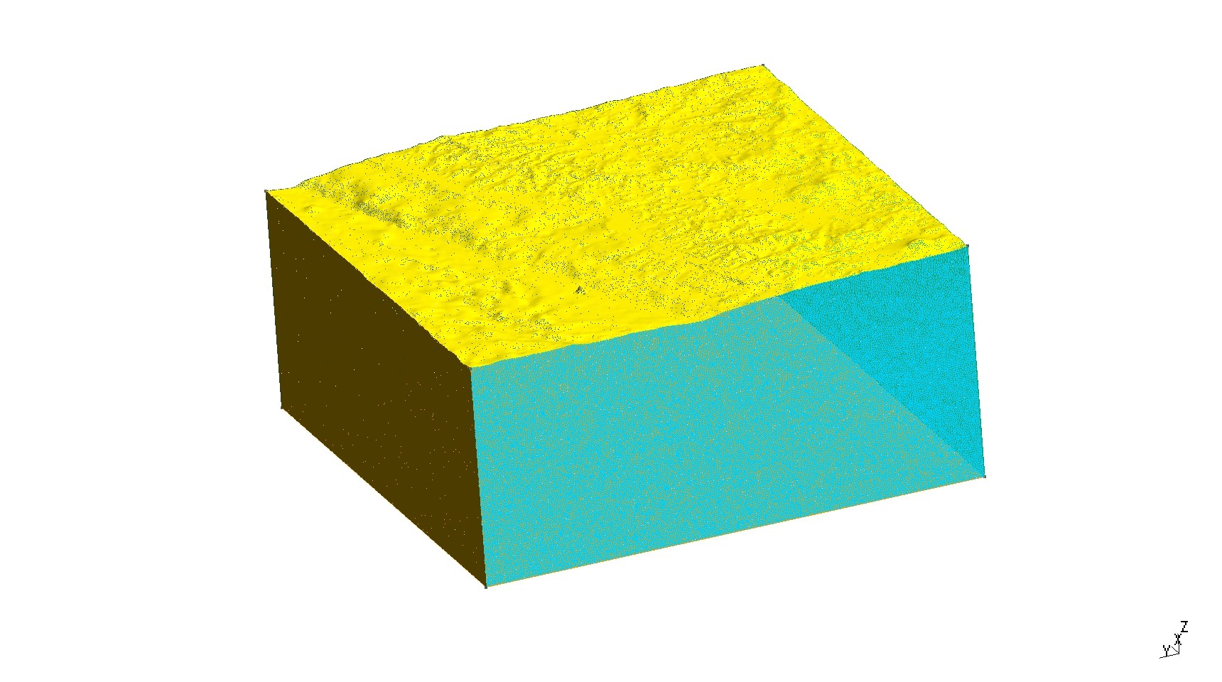
The new geometry with topography:

Diagram showing the geometry with topography.
5. Generate MSH mesh with the command line:
& gmsh step2.geo -3 -optimize_netgen -o step2.msh
option optimize_netgen is necessary for optimizing meshing with good quality.