SCEC TPV5#
TPV5 is the first SCEC benchmark. It has spontaneous rupture on a vertical strike-slip fault in a homogeneous halfspace. There are slightly heterogeneous initial stress conditions. The earthquake rupture is artificially nucleated in a square zone at the center of the fault surface. The rupture then spontaneously propagates over the rest of the fault surface. As it propagates away from the nucleation zone, it encounters two square patches with initial stress conditions that are different from the rest of the fault surface.

Fig. 12 Diagram of TPV5. The central square patch is the nucleation zone, while pink and green patches with higher and lower initial stress than neighbor region, respectively.#
Geometry#
The fault within the three-dimensional medium is a vertical right-lateral strike-slip planar fault that resides in a half-space. The fault reaches the Earth surface. The rupture is allowed within a rectangular area that is 30000 m long \(\times\) 15000 m deep. The bottom boundary of and the right and left ends of the allowed 30000 m \(\times\) 15000 m rupture area are defined by a strength barrier. The nucleation point is centered both along-dip and along-strike of the 30000m \(\times\) 15000m rupture area, on the fault plane, at 15000m along-strike and 7500m depth.
The mesh is generated in GMSH. All the files that are needed for the
simulation are provided.
The tpv5.geo file contains the geometry for
the fault in a cubit region.
To convert it to a SeisSol input, two steps are necessary:
Let GMSH mesh the
geofile:
$ gmsh tpv5.geo -3 -optimize -o tpv5.msh
Then, convert the GMSH file to the PUML format for SeisSol by:
$ pumgen -m msh2 tpv5.msh tpv5
The compilation and usage of PUMGen can be found in SeisSol/PUMGen and https://seissol.readthedocs.io/en/latest/ The geometry file (.geo) can be found at SeisSol/Examples. The mesh file can also be generated using the bash file SeisSol/Examples which essentially follows the same two steps (running GMSH and PUMgen) as described above.
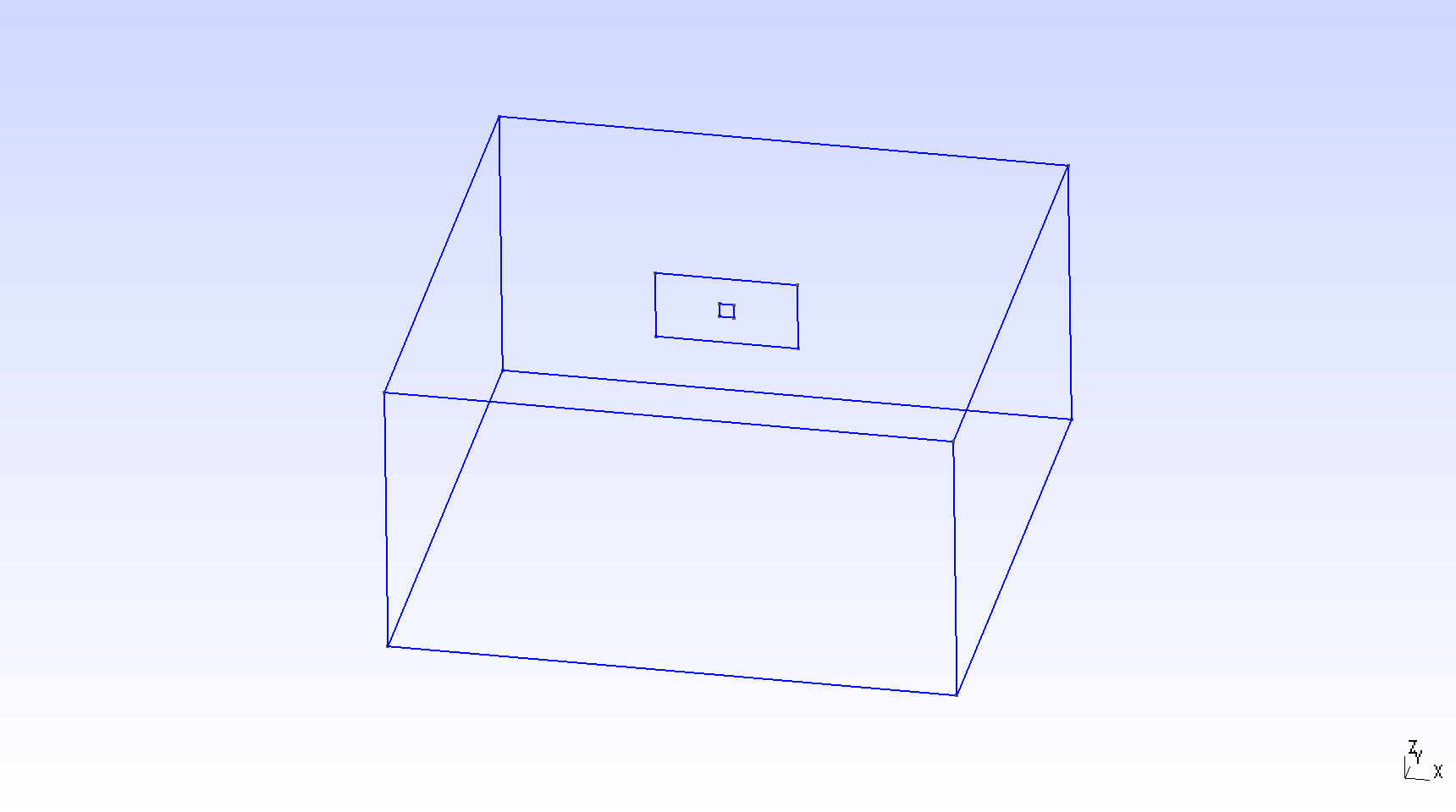
Fig. 13 Diagram of fault geometry of TPV5. The fault is 30000 m long and 15000 m wide. The square patch has a side-length of 3000m.#
Parameters#
Nucleation#
Nucleation occurs because of the initial shear stress in a 3000 m \(\times\) 3000 m square nucleation patch is set to be higher than the initial static yield stress in that patch. Failure occurs everywhere on the fault plane, including in the nucleation patch, following a linear slip-weakening fracture criterion.
TPV5 uses a linear-slip weakening friction everywhere on the fault.
There are ten parameters associated with the friction constitutive law
and fault properties in the parameters.par.
It can be found at SeisSol/Examples.
Four friction constitutive parameters are: mu_s, mu_d, d_c and cohesion. Six stress parameters are: s_xx, s_yy, s_zz, s_xy, s_xz, and s_yz. All the parameters are homogeneous on the fault except for the nucleation patch in the center of the fault, where s_xy is larger compared with that elsewhere. The parameters in TPV5 are listed in Table 1.
Parameter |
Description |
Value |
Unit |
|---|---|---|---|
mu_s |
static friction coefficient |
0.677 |
dimensionless |
mu_d |
dynamic friction coefficient |
0.525 |
dimensionless |
d_c |
critical distance |
0.40 |
m |
cohesion |
friction cohesion |
0.0 |
MPa |
s_yy |
stress |
120 |
MPa |
s_xx,s_zz,s_yz,s_xz |
stress |
0 |
MPa |
s_xy |
outside the nucleation zone |
70 |
MPa |
inside the nucleation zone |
81.6 |
MPa |
Notice that there are two patches with different initial stress: the one centered at (+7.5, -7.5) has 62 MPa and (-7.5, -7.5) has 78 MPa. This initial stress is included in the fault.yaml file.
Results#
All examples here generate surface and volume output files that can be visualized with ParaView.
The output folder contains a series of files for
fault dynamic rupture (hdf5 and .xdmf), wavefield (hdf5 and .xdmf),
on-fault receiver (.dat) and off-fault receivers (.dat).
The fault dynamic rupture and wavefield files can be loaded in Paraview.
For example, open Paraview and then go through File >> import >> prefix-fault.xdmf.

Fig. 14 Fault slip rate in the along-strike direction (SRs) at 4 seconds in TPV5, illustrated in Paraview.#
In the wave filed output file (prefix.xdmf, prefix_vertex.h5 and
prefix_cell.h5), the variables are shown in Table 2.
Index |
Parameter |
Description |
|---|---|---|
1 |
U |
displacement in x-axis |
2 |
V |
displacement in y-axis |
3 |
W |
displacement in z-axis |
4 |
u |
particular velocity in x-axis |
5 |
v |
particular velocity in y-axis |
6 |
w |
particular velocity in z-axis |
In the fault dynamics output file (prefix-fault.xdmf,
prefix-fault_vertex.h5 and prefix-fault_cell.h5), the variables are
shown in Table 3.
Index |
Parameter |
Description |
|---|---|---|
1 |
SRs and SRd |
slip rates in strike and dip direction |
2 |
T_s, T_d, P_n |
transient shear stress in strike and dip direction, transient normal stress |
3 |
U_n |
normal velocity (note that there is no fault opening in SeisSol) |
4 |
Mud, StV |
current friction and state variable in case of RS friction |
5 |
Ts0,Td0,Pn0 |
total stress, including initial stress |
6 |
Sls and Sld |
slip in strike and dip direction |
7 |
Vr |
rupture velocity, computed from the spatial derivatives of the rupture time |
8 |
ASl |
absolute slip |
9 |
PSR |
peak slip rate |
10 |
RT |
rupture time |
11 |
DS |
only with LSW, time at which ASl \(>\) d_c |